
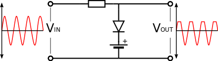
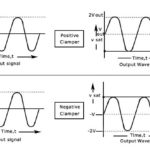
In electronics, a clipper is a device designed to prevent the output of a circuit from exceeding a predetermined voltage level without distorting the remaining part of the applied waveform.
A clipping circuit consists of linear elements like resistors and non-linear elements like junction diodes or transistors, but it does not contain energy-storage elements like capacitors. Clipping circuits are used to select for purposes of transmission, that part of a signal wave form which lies above or below a certain reference voltage level.
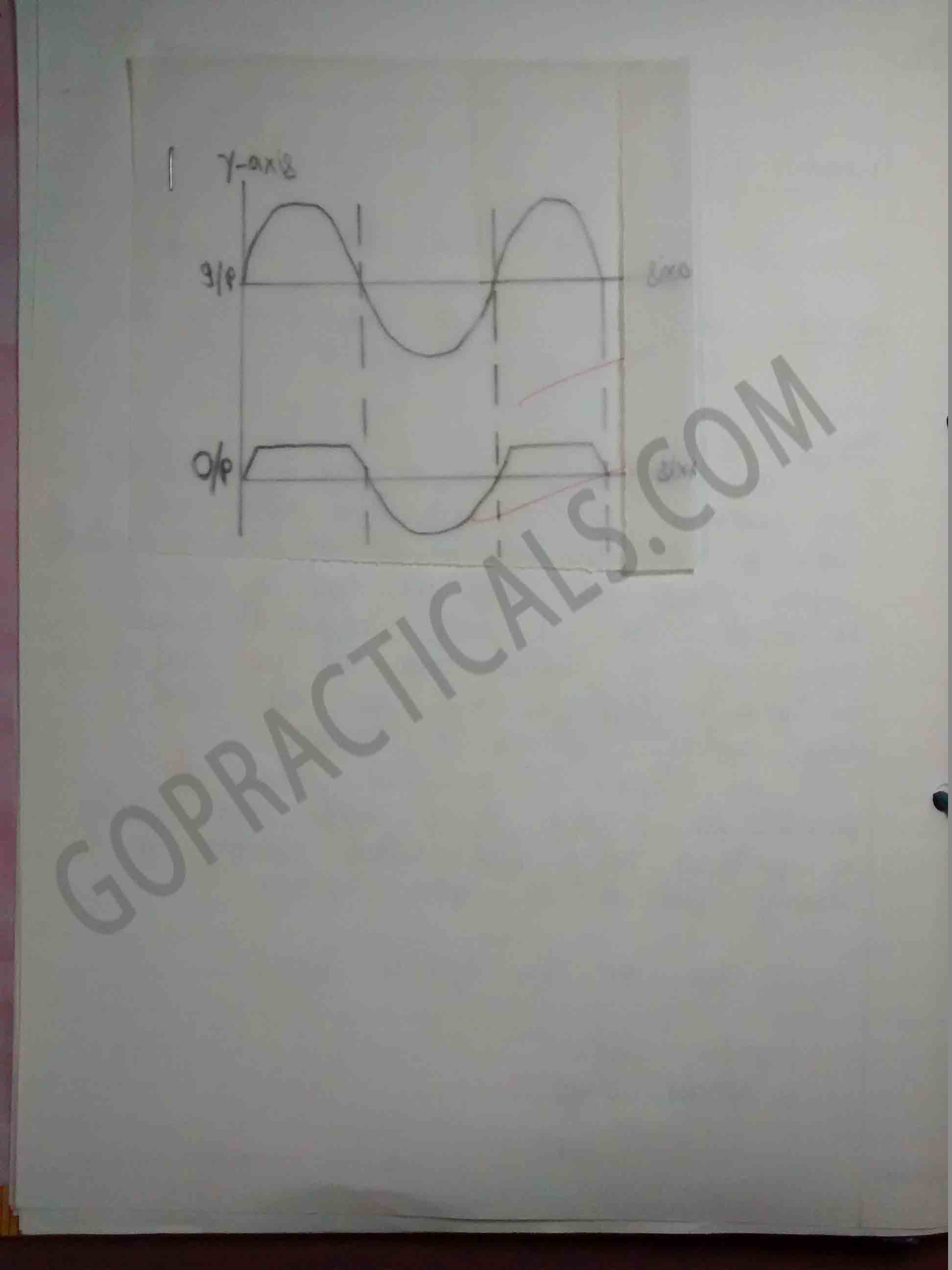
Thus a clipper circuit can remove certain portions of an arbitrary waveform near the positive or negative peaks. Clipping may be achieved either at one level or two levels. Usually under the section of clipping, there is a change brought about in the wave shape of the signal.
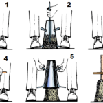
Practical to study the working of clipper circuit
Watch this Video to know more about clipper circuit
Also Check Out – Consistency of Concrete by Slump Cone
Thanks for visiting us…
Truly helpful